Foil model
The Foil structure is a parametric model of a single element foil section. That is, it is defined using (relatively) few parameters that are later used in a simple mathematical model to compute lift and drag for arbitrary angles of attack.
Why a parametric model?
Other implementations of lifting line and actuator line methods often use data based models for computing the lift and drag coefficients. That is, the user must supply data on how the lift and drag varies as a function of the angle attack, and then the solver can use this data together with interpolation or table look-up to compute force coefficients for arbitrary angles.
A data based approach is often fine, and does have some benefits. For instance, it is the only way to make a truly general model where the user have full control over the behavior of the sectional model. For this reason, there might be implementations of pure data based models in Stormbird in the future. However, the choice of using a parametric model for now where based on three reasons.
First, it becomes easier to use a parametric model as a building block for more complex foil models, where the behavior depends on some internal state, such as flap angle or suction rate. This is because the model parameters can be allowed to depend on the internal state through interpolation. See the varying foil sub chapter for more on this.
Second, a parametric model ensures smoothness, which is beneficial when using the model together with gradient based optimization algorithms. For instance, such a method might be used to optimize the angle of attack for wing sails at a given wind direction. The smoothness is in particular practical when the expected optimal point is close to the stall angle - which it often is.
Third, tuning a parametric models is generally believed to be easier than a data based model. For instance, lets say you want to adjust the exact stall characteristics of a 2D model, to make a simplified lifting line model better fit with high-fidelity experimental data; this would not be straightforward with a data based model, but should be fairly easy if the parametric model of the lift has good parameters to control the stall behavior.
The downside of a parametric model is believed to be small, as long as the model can represent typical foil section behavior without too many simplifications. The design of the Foil model is intended to achieve this as best as possible1.
Model overview
The model is divided in two core sub-models, labeled pre-stall and post-stall, respectively representing the behavior before and after the foil has stalled due to too high angle of attack.
For angles of attack below stall, it is assumed that both lift and drag can be represented accurately with simple polynomials. The lift is linear by default, but can also have an optional high-order term where both the factor and power of the term is adjustable. The high order term is meant to capture slowly developing separations, which might occur at low Reynolds numbers. The drag is assumed to be represented as a second order polynomial. For a wing sail operating below stall, the drag will mostly be dominated by lift-induced drag forces. The viscous drag can therefore be kept simple, as the importance to the total force is relatively low.
For angles of attack above stall, both the lift and drag are assumed to be harmonic functions which primarily is adjusted by setting the max value after stall. This is a rough model which might not be perfect for all angles of attack, but is assumed to be close enough. A rough and approximate model for the post-stall behavior is assumed to be OK as wing sails and suction sails will most often operate below stall.
The transit between the two models is done using a sigmoid function, where both the transition point and the width of the transition can be adjusted.
In addition, there factors in the model to account for added mass and lift due to the time derivative of the angle of attack. Both these effects are assumed to be linear for simplicity.
Available parameters
A view of the available fields in the Foil model is seen below, with further explanation of each parameter right after:
#![allow(unused)]
fn main() {
pub struct Foil {
    pub cl_zero_angle: f64,
    pub cl_initial_slope: f64,
    pub cl_high_order_factor_positive: f64,
    pub cl_high_order_factor_negative: f64,
    pub cl_high_order_power: f64,
    pub cl_max_after_stall: f64,
    pub cd_min: f64,
    pub angle_cd_min: f64,
    pub cd_second_order_factor: f64,
    pub cd_max_after_stall: f64,
    pub cd_power_after_stall: f64,
    pub cdi_correction_factor: f64,
    pub mean_positive_stall_angle: f64,.
    pub mean_negative_stall_angle: f64,
    pub stall_range: f64,
    pub cd_bump_during_stall: f64,
    pub cd_stall_angle_offset: f64,
    pub added_mass_factor: f64,
}
}
An explanation of the parameters are given below:
cl_zero_angle: Lift coefficient at zero angle of attack. This is zero by default, but can be set to a non-zero value to account for camber, flap angle or boundary layer suction/blowing.cl_initial_slope: How fast the lift coefficient increases with angle of attack, when the angle of attack is small. The default value is \( 2 \pi \) , which should always be the values used for a normal foil profile - with or without camber and flap - but it can also be set to different value for instance to account for boundary layer suction/blowing.cl_high_order_factor_positive/negative: Optional proportionality factor for adding higher order terms to the lift when the angle of attack is either positive or negative. Is zero by default, and therefore not used. Can be used to adjust the behavior of the lift curve close to stall.cl_high_order_power: Option power for adding higher order terms to the lift. Is zero by default, and therefore not used. Can be used to adjust the behavior of the lift curve close to stall.cl_max_after_stall: The maximum lift coefficient after stall.cd_min: Minimum drag coefficient when the angle of attack is equal to theangle_cd_min.angle_cd_min: The angle where the the minimum drag coefficient is reached.cd_second_order_factor: Factor to give the drag coefficient a second order term. This is zero by default.cd_max_after_stall: The maximum drag coefficient after stall.cd_power_after_stall: Power factor for the harmonic dependency of the drag coefficient after stall. Set to 1.6 by default.cdi_correction_factor: factor that can be used to correct for numerical errors in the lift-induced drag. Set to a positive value to increase the drag, and a negative value to decrease the drag. The default is zero, which means no correction.mean_positive_stall_angle: The mean stall angle for positive angles of attack, which is the mean angle where the model transitions from pre-stall to post-stall behavior. The default value is 20 degrees.mean_negative_stall_angle: The mean stall angle for negative angles of attack, which is the mean angle where the model transitions from pre-stall to post-stall behavior. The default value is 20 degrees.stall_range: The range of the stall transition. The default value is 6 degrees.cd_bump_during_stall: Factor to model additional drag when the foil is stalling, but that is not included in the pre- and post-stall drag models. Set to zero by default.cd_stall_angle_offset: Optional offset to the stall angle for the drag coefficient. This can be used to tune the drag curve to better fit experimental data. The default is zero, which means that stall effects on the drag starts at the same angle of attack as for the lift. When the offset is set to any value, the "amount of stall" function is shifted by this value for the case of the drag coefficient only.added_mass_factor: Factor to model added mass due to accelerating flow around the foil. Set to zero by default.
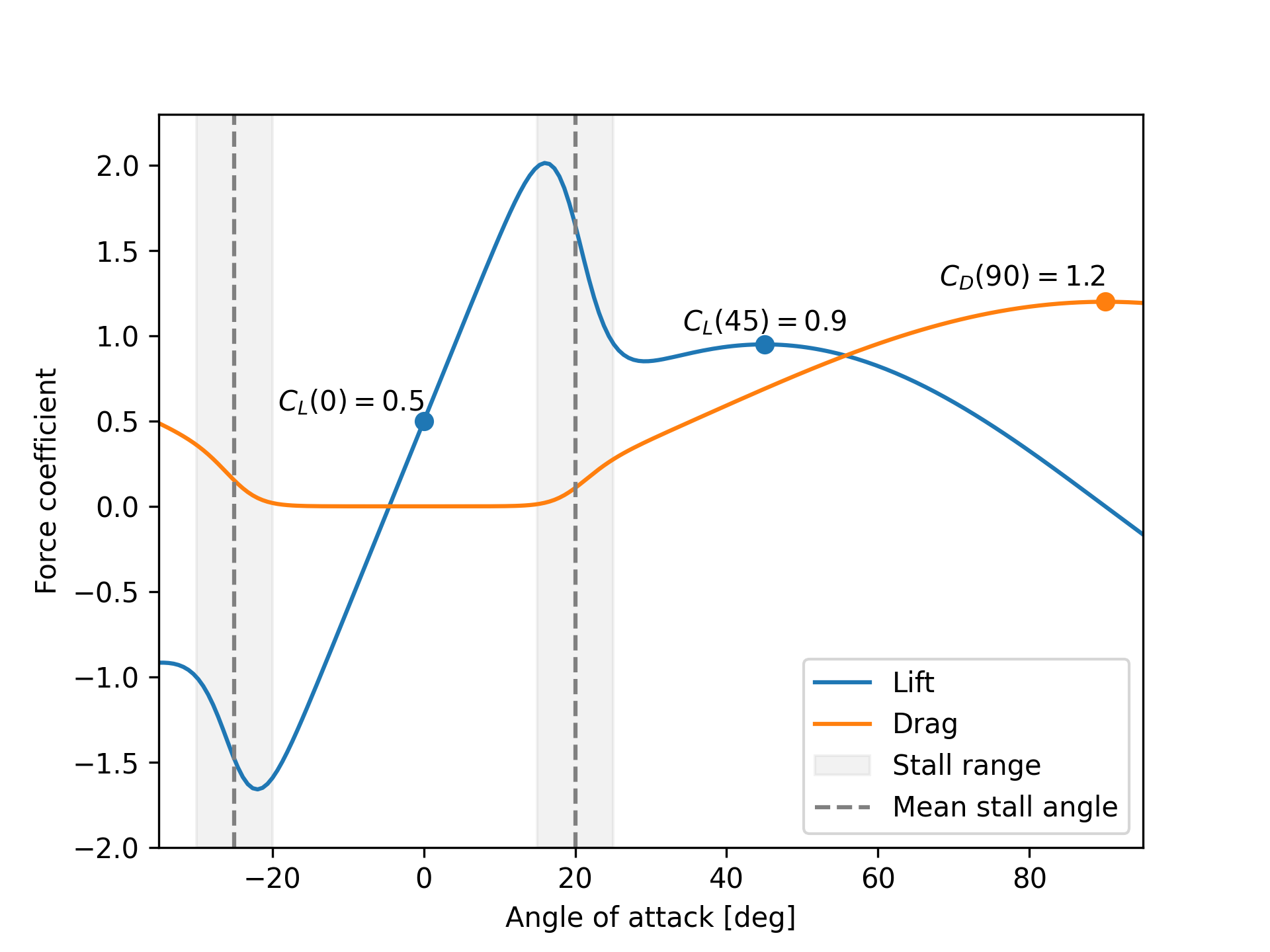
Example
An example of the output of a foil model is shown below. The parameters values are given as follows:
#![allow(unused)]
fn main() {
let foil = Foil {
    cl_zero_angle = 0.5,
    cl_max_after_stall = 0.9,
    cd_max_after_stall = 1.2,
    mean_positive_stall_angle = 20.0_f64.to_radians(),
    mean_negative_stall_angle = 25.0_f64.to_radians(),
    stall_range = 10.0_f64.to_radians(),
    ..Default::default()
}

}
-
The design of the
Foilmodel is open for changes, and may be updated when a need is discovered. The goal is to find the right balance between simplicity and flexibility. ↩